


What is CAD?
CAD is the abbreviation for Computer-Aided Design, which refers to the process of using computer software and hardware technologies to create, modify, analyze, and optimize design drawings or models. It is widely used in fields such as engineering, architecture, and manufacturing.
Function Entry
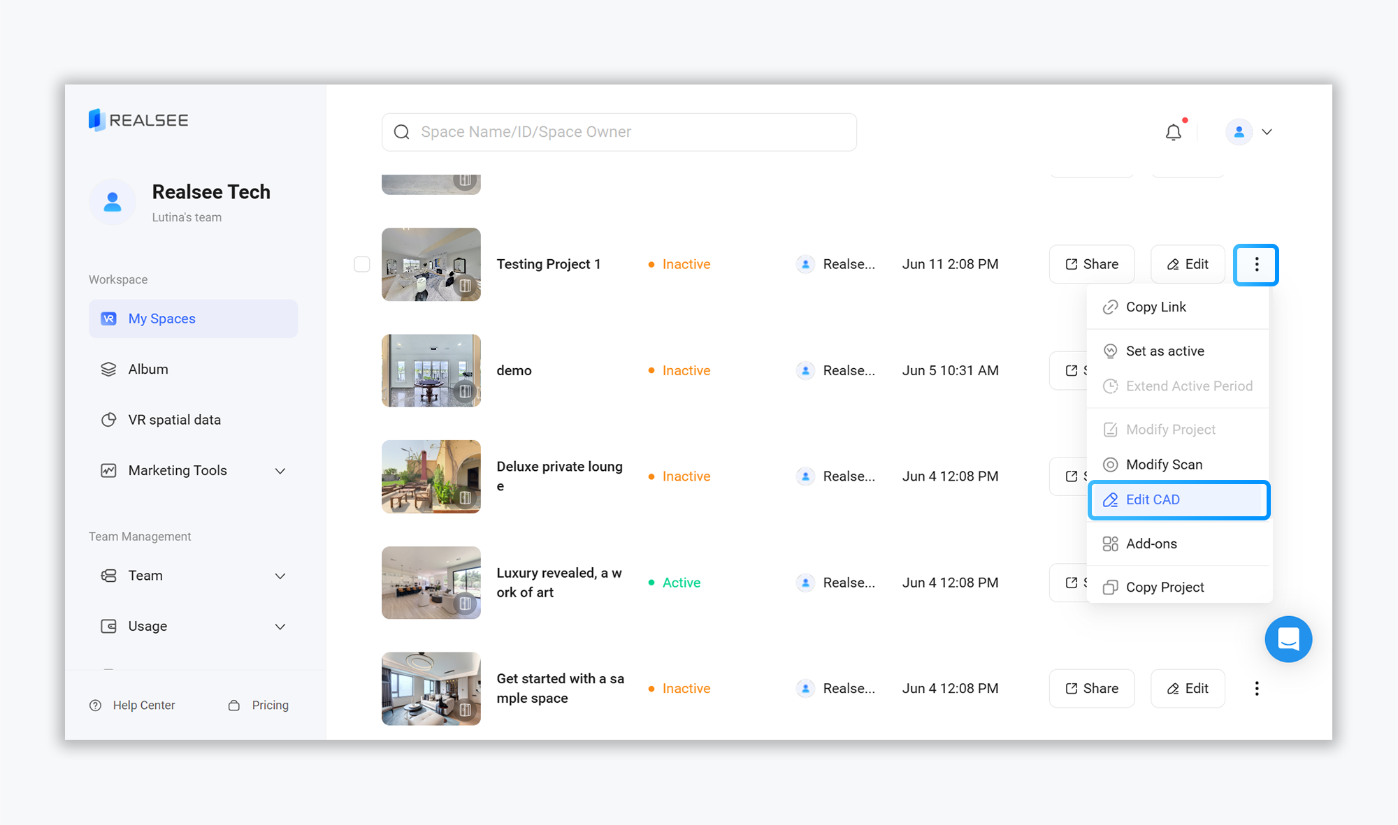
Access the console admin backend, click on the "My Spaces" feature in the left-hand menu bar. On the 3D Tour list page, select the project you want to edit. Locate the "More Settings" option on the right side of the project, then click "Edit CAD" to enter the CAD editor for modifying and optimizing the auto-generated results.
Canvas Instructions
- Content Editing
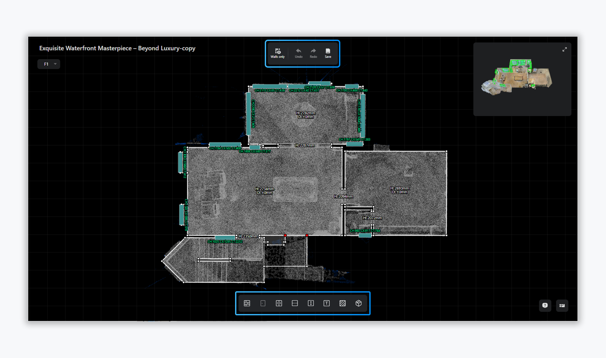
Central Canvas:
- The base layer is a VR top-down view.
- Typically, you’ll need to adjust wall lines to align them with the edges of the top-down view.
Project Name:
- The current project name is displayed in the top-left corner of the left-side canvas.
Top Toolbar:
- Perform file-level actions like Undo, Redo, and Save.
Bottom Element Bar:
- Tools for drawing and adding objects to the file.
- VR Reference Tools
Side Reference Panel
- A colorized VR view is provided on the right panel for visual reference during editing
- Verify details by cross-checking with the color VR display
Split View Mode
- Toggle split-screen mode using the button in the top-right corner
- Enables detailed inspection through enlarged view for precise adjustments
Feature Instructions
- Wall Drawing
Adding New Walls
- Click the "Draw Wall" button in the bottom toolbar using the left mouse button to initiate wall drawing
- Supports numeric input for precise dimensional editing
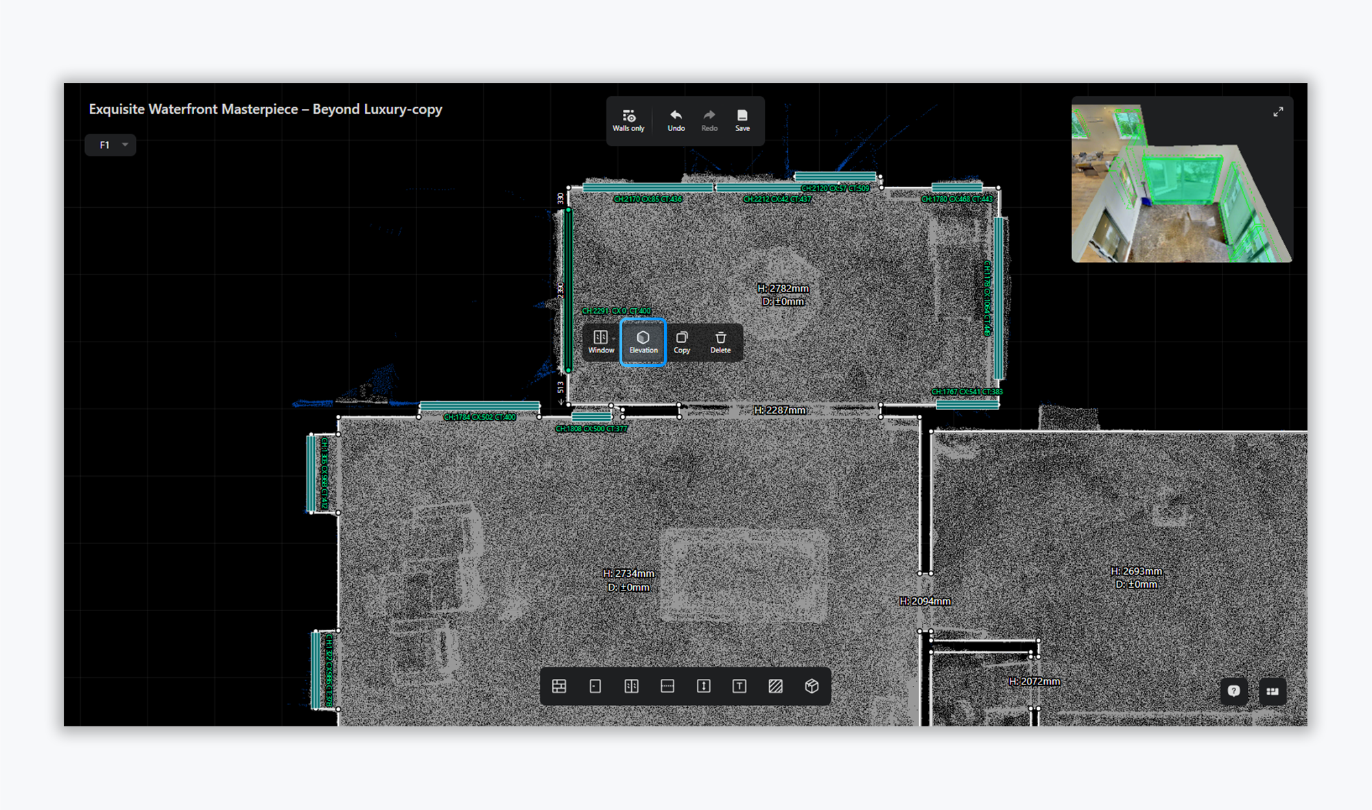
Adjusting Walls
- Click and drag a wall with the left mouse button to reposition it
- The VR reference view will display a colored highlight at the selected wall's location
- Drawing Doors & Windows
Adding New Doors/Windows
- Click the Door/Window button in the toolbar with the left mouse button
- Place the element by clicking on the target wall
Reposition doors/windows
- Left-click and drag to reposition doors/windows, with support for switching to elevation view to precisely edit width/height parameters while maintaining real-time VR reference updates
- Line Annotation
- Click the Dashed Line button to add annotations to the canvas
- Drag existing dashed lines to reposition them as needed
- Height Dimensioning
- Click the Height Dimension button to add auto-calculated height measurements on the canvas
- Text Annotation
- Click the Text Label button to add text annotations anywhere on the canvas
- Area/Perimeter Annotation
- Click the Area/Perimeter button to enter region selection mode
- Select the target region - the system will automatically calculate and display area and perimeter measurements upon completion
- Object Annotation
- Click the Annotate Objects button to expand the object list panel on the left side of the canvas
- Left-click on any object in the list to place it on the canvas
Q1: How can I switch between imperial and metric units in a CAD editor?

Q2: In the manual floor plan editor interface, what do the "red dots" appearing at line endpoints or intersections represent?

A: Red dots indicate that "the wall segments are unclosed" or "the endpoint is not fully snapped to an anchor point."
When drafting and adjusting floor plans, the system requires all wall segments of a room to form a completely closed loop. This ensures proper calculation of room areas, accurate definition of spatial boundaries, and high precision in generated CAD deliverables.
-
Meaning of the Red Dots: When an endpoint appears in red, it signifies that the segment at this position is currently disconnected, floating, or not tightly stitched to the adjacent wall.
-
Potential Impact: Unclosed red dots will prevent the system from identifying the area as an independent room, which may affect subsequent automated spatial rendering and the export precision of CAD files.
If you encounter any issues, need assistance, or have feedback regarding the use of Realsee products, please feel free to contact us via email at lutina.suen@realsee.ai.